In recent years, I have visited many modern farms and agricultural technology parks. One strong impression I have gained is that agriculture is rapidly shifting from an experience-based model of “depending on the weather” to a data-driven precision model.
During this transformation, how to reliably and efficiently collect sensor data distributed across vast farmland and transmit it to a control center with low power consumption has always been a core challenge for technology implementation.
Traditional Wi-Fi has limited coverage, while 4G/5G modules usually come with higher power consumption and costs. Meanwhile, a wireless technology called LoRa is gradually taking root in smart agriculture with its unique advantages.
In this article, based on several real projects I have participated in, I would like to discuss how LoRa modules are practically applied in agricultural environmental monitoring and remote control systems, and how they move from technical drawings into real farmland.
Whether you are an engineer from an agricultural technology company or an architect of IoT solutions, I hope these practical field experiences can provide useful insights.
Why LoRa? Wireless Communication Selection Logic in Smart Agriculture
When designing an IoT architecture for hundreds of acres of farmland, the choice of communication technology directly determines the feasibility, cost, and long-term maintenance difficulty of the entire system.
You may already be familiar with technologies such as Zigbee, NB-IoT, and Wi-Fi. However, in agricultural scenarios, LoRa often stands out because it precisely addresses several key pain points of agricultural applications.
First, coverage range is a critical requirement.
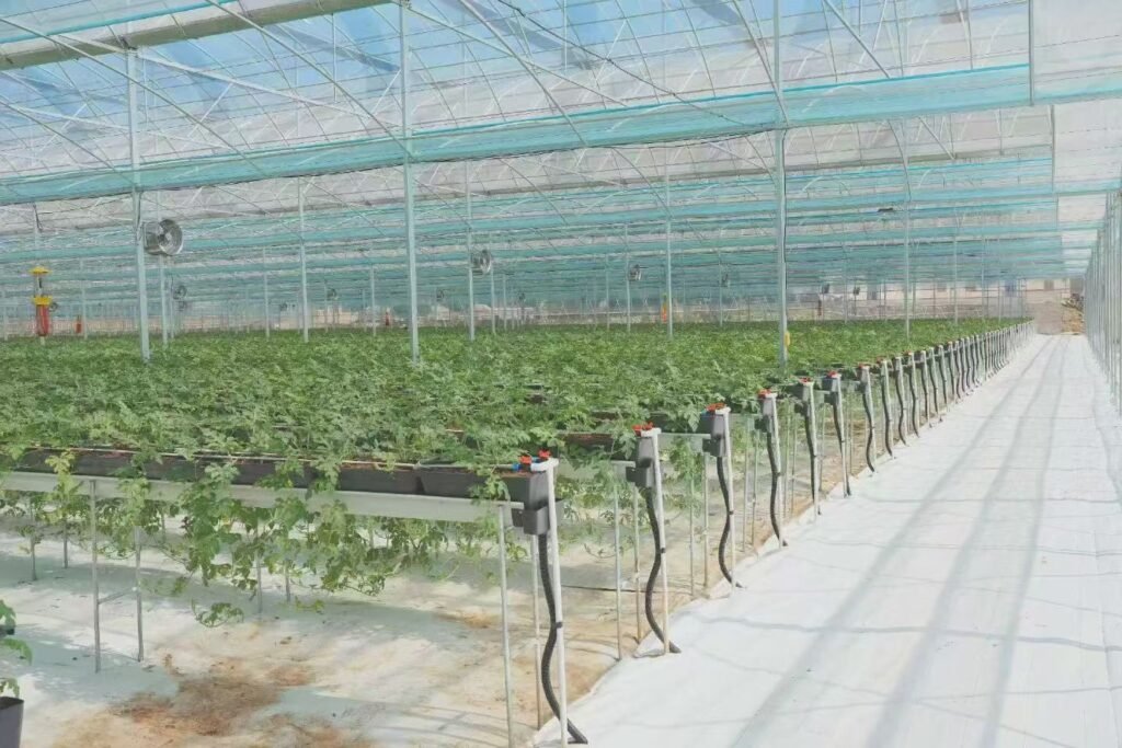
A standard LoRa module can easily achieve a communication distance of 1–3 km or even longer in an open environment. This means that in flat farmland areas, only a few concentrators (gateways) are needed to cover the entire area.
In comparison, Zigbee usually has an effective communication distance of only several dozen meters to around one hundred meters, requiring a large number of relay nodes. This not only increases hardware costs but also makes network topology and maintenance more complicated.
Note: The term “open environment” is an important condition. In actual farmland, crops (especially tall crops such as corn) can create signal obstruction as they grow. Therefore, when planning gateway locations, it is necessary to consider crop height changes throughout the growth cycle and install antennas at sufficient heights in advance.
Second, power consumption directly affects deployment lifetime.
Many agricultural sensor nodes rely on battery power and are expected to operate continuously for one or even multiple crop growth seasons (more than six months).
Due to its unique communication method, LoRa technology can achieve extremely low power consumption in receiving mode and supports mechanisms such as “wake-on-radio,” allowing nodes to remain in deep sleep most of the time and only wake up when data transmission or reception is required.
Based on our actual testing, nodes equipped with suitable batteries can operate stably for more than 18 months when reporting data once every hour.
Finally, cost and deployment flexibility should not be ignored.
LoRa operates in license-free ISM frequency bands without requiring spectrum fees. The module cost itself has also become very affordable.
More importantly, users can build a completely private LoRa network, keeping all data on their own servers. This is a major advantage for agricultural enterprises that value data security and customized requirements.
To make the comparison clearer, the following table shows key parameters of different technologies in agricultural scenarios:
| Technical Indicator | LoRa | NB-IoT | Zigbee | 4G Cat.1 |
|---|---|---|---|---|
| Typical Coverage Radius | 2–5 km (suburban areas) | 1–10 km | 10–100 m | 1–5 km |
| Power Consumption Level | Extremely low (battery life measured in years) | Low (battery life measured in months/years) | Low (battery life measured in months) | Medium to high (usually requires external power supply) |
| Data Transmission Rate | Low (0.3–50 kbps) | Low (~100 kbps) | Medium (250 kbps) | High (Mbps level) |
| Network Deployment | Private network / public network | Operator public network | Private network | Operator public network |
| Node Cost | Low | Medium | Low | Medium |
| Suitable Applications | Wide-area, low-frequency, fixed data reporting | Wide-area, low-frequency, mobility support | Local-area, medium-frequency, self-organizing network | Wide-area, high-frequency, high real-time requirements |
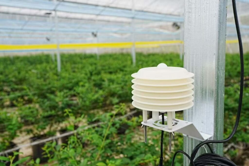
From the table, we can clearly see that mainstream smart agriculture applications, such as environmental data collection (temperature, humidity, soil moisture, light intensity) and status control (valve switching), usually involve small data volumes, low reporting frequency, and fixed node locations.
LoRa provides the best balance between coverage, power consumption, and cost, making it one of the most cost-effective choices available today.
Practical Starting Point: Building a Basic Soil Temperature and Moisture Monitoring Node
After discussing the theory, let’s start building the most basic unit: an independently operating LoRa soil temperature and moisture monitoring node.
This node consists of sensors, a microcontroller unit (MCU), and a LoRa module.
Hardware Connection and Power Supply Design
Hardware connection is the first step, but more importantly, proper power supply planning is critical. Agricultural environments are complex, and power stability should always be the primary consideration.
Core component list:
Main MCU: Low-power model with sufficient resources
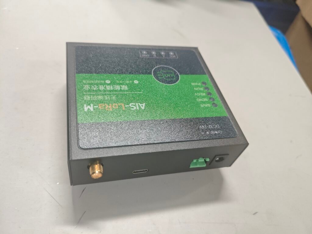
LoRa Module: Based on mainstream chips, operating at the 433MHz frequency band
Sensor: RS485 soil temperature and moisture sensor (strong anti-interference capability and long transmission distance)
Power Supply: Primary lithium battery + solar panel (optional)
When connecting the system, attention should be paid to several working mode pins of the LoRa module. These pins are mainly used to switch between “communication mode” and “configuration mode,” as well as indicate the current operating status of the module, allowing the main controller to manage power consumption more efficiently.
Power supply design is the key to success.
I strongly recommend using a “main battery + solar panel supplement” solution. Lithium batteries have an extremely low self-discharge rate, making them highly suitable for long-term outdoor applications.
When calculating power consumption, it is important to distinguish between “active current” and “sleep current.”
Taking our node as an example, assuming data is collected and transmitted every 15 minutes, and each active working period lasts 5 seconds.
Under this working mode, a 6000mAh battery can theoretically provide more than 1 year of operation. With an added solar panel, several years of maintenance-free operation can easily be achieved.
Firmware Logic and Low-Power Programming
After the hardware is ready, the next step is making the node work “smartly.” The core principle is allowing the device to stay in sleep mode most of the time and only wake up when necessary.
The main program loop logic should work as follows:
Enter deep sleep mode:
Wake up through an internal timer according to the configured data collection interval (such as 15 minutes).
After waking up:
Initialize the sensor and LoRa module.
Collect sensor data:
Read soil temperature and moisture data through the RS485 interface.
Package and transmit data:
Send the data wirelessly through the LoRa module.
Briefly enter receiving mode:
Wait for possible acknowledgments or control commands.
Turn off power to all peripherals and prepare for the next sleep cycle.
The key technique here is that during data transmission, the main controller uses the module’s status indication pins to determine whether transmission has started or completed, allowing it to enter sleep mode while waiting.
As a result, during most of the data transmission process, the main controller remains in sleep mode and only wakes up briefly at the beginning and end of transmission, greatly reducing power consumption.
This is an essential technique for achieving ultra-long battery life.
Network Architecture and Data Aggregation: Building a System from Individual Nodes to Large-Scale Deployment
Getting a single node working properly is only the first step.
Smart agriculture requires a network consisting of dozens or even hundreds of nodes. How to efficiently and reliably aggregate data to the cloud or a local server becomes the next challenge.
Here we discuss two typical LoRa network architectures.
Star Network and Gateway Deployment
This is the simplest and most commonly used architecture.
All terminal nodes communicate directly with one or multiple LoRa gateways. The gateway then uploads data to the server through Ethernet, 4G, or other communication methods.
Golden rules for gateway deployment:
Prioritize height:
Install gateway antennas at relatively high locations within the farm area, such as warehouse roofs or observation towers.
Avoid metal obstacles:
Try to avoid large metal sheds, water tanks, and other objects that strongly reflect or block wireless signals around the antenna.
Channel planning:
If there are a large number of nodes, multiple gateways can be considered, with each operating on different frequency channels to reduce interference.
At the software level, the core task of the gateway is protocol conversion.
It receives LoRa wireless frames, parses them, packages them into standard protocols such as JSON or MQTT, and sends them to the cloud platform.
At the same time, the gateway can record the signal strength and signal-to-noise ratio (SNR) of each data packet.
By monitoring these values over time, you can determine whether node batteries are degrading, antennas are damaged, or new obstacles are affecting signal transmission, enabling predictive maintenance.
Exploration of Relay and Mesh Networks
In extremely large farms or areas with complex terrain (such as hills and orchards), a star network may not be able to cover every corner.
In this situation, certain nodes can be considered as relay nodes.
A simple application-layer relay strategy is allowing some nodes with sufficient power supply to act as “regional aggregation points.”
Other nodes send data to these aggregation points, which then collect and forward the data to the remote gateway.
This requires your communication protocol to include a “target address” field.
Note:
Relay significantly increases network latency and overall power consumption because the same data needs to be transmitted twice. It also requires careful routing protocol design to avoid loops and conflicts.
For most small and medium-sized smart agriculture projects, optimizing gateway placement is simpler and more effective than introducing relay mechanisms.
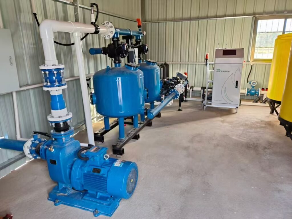
From Monitoring to Control: Achieving Safe Remote Irrigation Control
Monitoring is perception, while control is execution.
The closed-loop system of smart agriculture ultimately relies on controlling actuators such as valves, water pumps, and curtain motors. When using LoRa for remote control, reliability and safety require special attention.
Two-Way Communication and Confirmation Mechanism
Monitoring data reporting is one-way communication. Losing an occasional data packet usually does not cause serious problems.
However, control commands must be successfully delivered. Therefore, two-way communication and command acknowledgment mechanisms are essential.
A reliable command delivery process works as follows:
Server sends command:
The server sends a control command through the gateway to the node with the specified address (for example, “open valve No.1”). The command should include a unique command ID.
Node confirms receipt:
After receiving the command, the node immediately replies with an acknowledgment signal containing the command ID, indicating “I have received it.”
Node executes and reports status:
The node executes the command (driving the relay to open the valve). After successful execution, it actively reports the status again (“Valve No.1 is open”).
Server timeout and retransmission:
If the server does not receive confirmation within the specified time, the command is considered lost, and the retransmission mechanism is triggered.
On the node side, after each data report, it briefly opens a receiving window to listen for commands from the server.
Once a command is received, the node responds immediately, forming a complete closed-loop control system.
Hardware Safety and Misoperation Prevention
Remote control involves the operation of physical equipment, so safety is the bottom line.
In addition to acknowledgment mechanisms at the communication protocol level, hardware-level protection must also be considered:
Relay status feedback:
Do not rely only on a single signal to control the relay.
It is better to use relays with status feedback contacts to confirm whether the action has actually been performed.
Interlock logic:
For high-power equipment such as water pumps, software interlock logic should be implemented in the program to prevent conflicting commands from being executed at the same time (such as opening the inlet valve and drainage valve simultaneously).
Local manual mode:
Keep physical switches or buttons on the control cabinet, allowing on-site operators to bypass the remote system and manually control equipment during emergencies.
This manual operation signal should also be detected and uploaded so that the server knows the system is currently operating in local manual mode.
Power isolation:
The power supply of the relay circuit controlling actuators should be isolated from the core communication components through optocouplers or magnetic isolation.
This prevents surge currents generated by inductive loads such as motors from damaging sensitive chips.
These detailed considerations are essential for ensuring long-term stable system operation.
Performance Optimization and Troubleshooting: Making the System More Robust
After the system is deployed, the work has only just begun.
How to optimize performance and quickly identify problems when they occur is where real engineering value appears.
Optimizing Data Transmission Efficiency
The selection of LoRa’s Air Rate is a balance.
A higher transmission rate means shorter sending time (lower power consumption), but it also reduces receiving sensitivity (shorter communication distance).
Based on our experience:
Fixed nodes with moderate distance (<2km):
A higher transmission rate can be selected to significantly shorten transmission time and improve energy efficiency.
Edge nodes or longer distances (>2km):
A lower transmission rate is recommended to ensure reliable communication links.
Extreme long-distance communication or obstacle penetration:
The lowest transmission rate may be required.
You can design a strategy where the gateway analyzes long-term node SNR data and sends downlink commands to adjust the node’s Air Rate.
Nodes with consistently good signal quality can increase transmission speed to save energy, while nodes with weaker signals can automatically reduce transmission speed to maintain connectivity.
Common Faults and Troubleshooting Checklist
When a node goes “offline,” troubleshooting can be performed step by step according to the following checklist:
Check power supply:
Measure the battery voltage. Check whether the solar panel connection is loose or whether the panel surface is covered by dust.
Monitor wireless signals:
Use another LoRa module and a simple debugging tool with the same configuration parameters to check whether signals are being transmitted.
This is the most direct way to determine whether the node is still “alive” and attempting communication.
Check configuration consistency:
Confirm that the node and gateway have exactly the same address, channel, and Air Rate settings.
This is one of the most common configuration mistakes.
Analyze signal quality:
If the gateway can receive the signal but the signal is weak, check whether the node antenna is properly connected, whether the antenna type matches, and whether the antenna is surrounded by metal objects or placed too close to the ground.
Check environmental factors:
Check whether newly built metal structures or growing tall crops have created new signal obstacles.
Once, a batch of our nodes went offline collectively after running for three months.
After troubleshooting, we found that the internal RC oscillator of the MCU drifted under low-temperature conditions, causing UART baud rate deviation and communication failure with the LoRa module.
Later, we changed all nodes to use an external crystal oscillator as the clock source, and the problem was solved.
This case shows that agricultural outdoor environments (-20°C to 60°C) have much higher requirements for component reliability compared with indoor laboratory conditions.
Small tip about antennas:
For underground soil sensor nodes, the antenna must be extended above the ground.
A flexible thin wire antenna can be fixed along a pole.
Never bury the antenna together with the sensor underground, because soil causes significant attenuation of RF signals.
Conclusion:
From a series of soil moisture data values to automatically activated irrigation valves, LoRa technology acts like an invisible neural network, bringing digital intelligence into traditional agriculture.
This system is not based on overly complicated theories, but rather continuous engineering optimization between power consumption, cost, reliability, and ease of use.
Every farm has different geographical environments, crop structures, and management methods.
The best solution is always the one that solves real problems and is accepted by both farm owners and technicians.
At the early stage of a project, it is better to start with a few nodes and a small gateway to build a minimum viable system.
Run it in real farmland conditions for one month, and the experience and lessons you gain will be far more valuable than one year of simulation in a laboratory.